Controller Area Network (CAN) - Layer#
Protocol Basics (ISO 11898-2)#
ISO 11898-2 is an international standard that defines the physical and data link layer requirements for Controller Area Network (CAN) communication. It’s commonly referred to as the “High-speed CAN” standard, used in automotive and industrial applications that require high-speed, reliable communication. The standard defines the physical layer requirements for a high-speed CAN bus, including the electrical characteristics of the bus, the signaling method, and the required cable types. It also defines the data link layer requirements, including the message format, error detection and handling, and communication protocol. The standard specifies a bit rate of up to 1Mbps, using a differential signaling method to transmit data over a twisted pair of wires. It also defines using a non-return-to-zero (NRZ) encoding scheme for data transmission, which provides increased noise immunity and improved signal quality. Additionally, the standard specifies the use of a cyclic redundancy check (CRC) for error detection and the use of an acknowledgment mechanism to ensure that messages are transmitted and received correctly.
Summary
Open standard protocol release in 1986 (revised in 1991 [RobertBGmbHa])
Multi-master serial bus
Two or more nodes are required
Two-wire bus
Termination resistors are required (e.g. 120 Ohm)
In the car the first and last ECU on the bus have a termination resistor

Fig. 19 CAN-Network overview. Author: EE JRW, CC BY-SA 4.0#
Differential signal
Wired AND
Low signal (0 Bit) is dominant
Logic analyzer just needs one wire to sniff communication
Bit stuffing:
To allow the bus participants to synchronize the communication, the maximum same consecutive symbols are five
If more equal consecutive bits are sent, after every 5th consecutive symbol a inverted stuffing bit is inserted
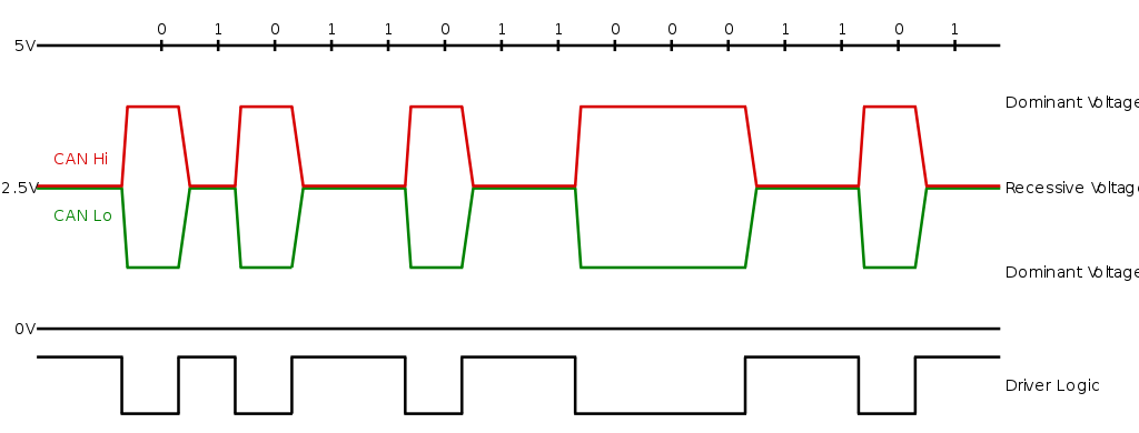
Fig. 20 CAN-Network overview. Author: EE JRW, CC BY-SA 4.0#
For engineering tools the D-SUB connector is used to connect to the CAN-bus, which is not present in the car.
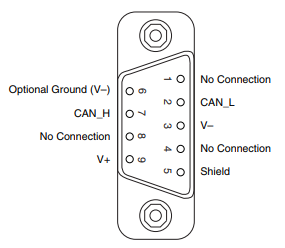
Fig. 21 D-SUB (DB9) pinout. (https://knowledge.ni.com/KnowledgeArticleDetails?id=kA00Z0000019YIGSA2)#
On Dual-CAN D-SUB interfaces, PIN 1 and PIN 8 are used to connect a second CAN-Bus.
PIN 1: CAN LOW
PIN 8: CAN HIGH
CAN-Node#
To understand low-level attacks on CAN-Networks, it’s required to know the role of the individual components of a CAN-Node.
Processing unit, microprocessor, host processor
Runs application firmware
Processes received messages from message boxes
Put messages to transmit into message boxes
CAN controller
Integrated into MCU or connected via SPI
TX: Generates bits from CAN-frames
RX: Generates CAN-frames from bits
Handles re-transmission, arbitration, bit-stuffing, CRC, acknowledgment
Mailbox system to MCU. Controller handles sending and receiving by itself
CAN Transceiver
Converts the logic signal to differential signal and vice versa
Puts the signal onto the bus
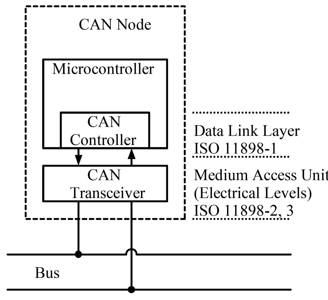
Fig. 22 CAN-Network overview. Author: EE JRW, CC BY-SA 4.0#
CAN frame on the wire#
A CAN (Controller Area Network) frame is a standardized data structure used to transmit and receive messages on a CAN bus. It is composed of several fields that are used to store the necessary information about the message being transmitted.
Start-of-frame: A dominant bit, indicating the start of a CAN message.
Arbitration: This is a unique identifier that is used to identify the message and its priority. The Remote Transmission Request (RTR) bit is part of the arbitration field. This bit is used to indicate whether the message is a data frame or a remote transmission request (RTR) frame. A data frame carries a data payload, while an RTR frame requests data from a specific node.
Control: This is a 6-bit field that indicates the type of message, such as a standard or extended frame, and the number of bytes of data payload that are present in the message.
Data: This is an array of up to 8 bytes that contains the data payload of the message.
CRC: The Cyclic Redundancy Check (CRC) field is used to ensure that the message has been transmitted without errors.
ACK: A dominant bit, indicating the successful reception of a message. This bit is transmitted by the receiver of the message.
End-of-frame: Seven recessive bits, without a stuffing bit.
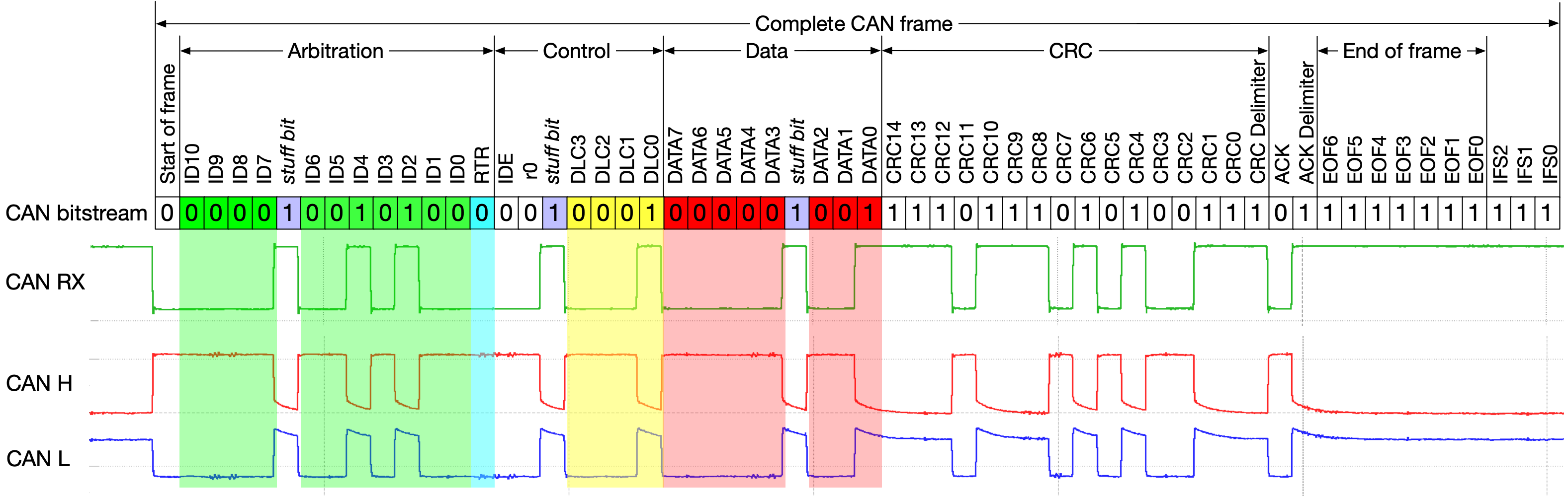
Fig. 23 CAN frame as transferred on the bus. Author: Dr. Ken Tindell#
CAN frame in memory#
Identifier (29-bit)
Control flags (3-bit)
Length (8-bit)
Payload (64-bit)
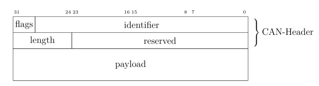
Fig. 24 CAN frame defined by SocketCAN#
Figure from [Gro20].
The Linux SocketCAN implementation of the Controller Area Network (CAN) frame (struct can_frame) is a data structure defined in the linux/can.h header file.
This structure is used to encapsulate the information that is required for the transmission and receipt of messages on a CAN bus.
The structure is composed of several fields that are used to store the relevant information about the message being transmitted
on the CAN bus, including:
can_id: A 32-bit identifier to uniquely identify the message and also used to indicate the type of the message, such as a standard or extended frame.can_dlc: An 8-bit data length code that indicates the number of bytes of data payload that are present in the message.data: An array of 8 bytes that contains the data payload of the message.
CAN-Controller State Machine#
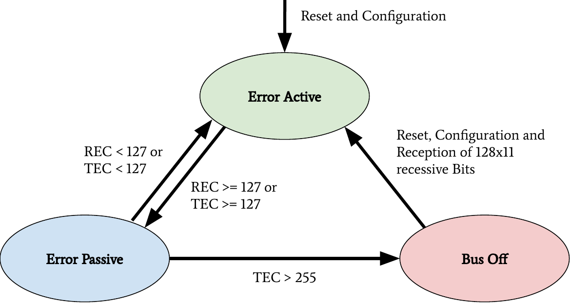
Fig. 25 CAN bus states on transmission errors. Receive Error Counter (REC), Transmit Error Counter (TEC). In Error Passive mode, a CAN-Controller will not send error frames in case of an error on the bus.#
In the Controller Area Network (CAN) protocol, error counters are used to track the number of errors that occur during message transmission. The Transmit Error Counter (TEC) and the Receive Error Counter (REC) are used to keep track of the errors at the transmitting and receiving nodes respectively:
The TEC and REC are used to monitor the error rate on the bus and based on the error rate different states are entered by the node.
Every CAN controller on the CAN-BUS is listening for errors.
When an error is detected, the discovering node transmits an Error Flag which destroys the bus traffic and the other nodes take appropriate action, i.e. discarding the current message and increasing the error counters.
In case of a transmission error, 8 error points are added to the TEC and for every received error 1 error point is added to the REC.
The TEC is incremented at a faster rate than the REC when a transmitter detects a fault. This is because the fault is most likely caused by the transmitter.
The node is considered to be in Error Active state when both TEC and REC are below 127. As soon as one of the counters exceeds this threshold, the node enters the Error Passive state. And if the TEC exceeds 255, the node enters the Bus-Off state.
An Error Active node transmits Active Error Flags, an Error Passive node transmits Passive Error Flags and a Bus Off node does not transmit anything on the bus.
For every successfully transmitted message, the TEC is decremented by 1 and for every successfully received message, the REC is decremented by 1.
Some CAN controllers provide status bits and corresponding interrupts for two states, “Error Warning” and Bus Off, and a few controllers also, provide direct access to the error counters.
CAN Arbitration CDMA/CR#
CAN (Controller Area Network) arbitration is the process of determining which device on the network has priority to transmit data. It is used to avoid collisions and ensure efficient communication between devices. CDMA (Code Division Multiple Access) is a technique used to allow multiple devices to share the same communication channel simultaneously. CR (Collision Resolution) is a method used to resolve conflicts or collisions that occur when two or more devices attempt to transmit data at the same time on a shared bus. CDMA/CR is used to improve the efficiency and reliability of CAN communication by resolving conflicts when they occur. This is done by using the CAN identifier as a priority system where devices with a higher priority (lower CAN identifier value) are allowed to transmit their data first. If a message could not be sent because a higher priority was sent simultaneously the sending of the message will be retried after the bus is free again until the message can be sent.
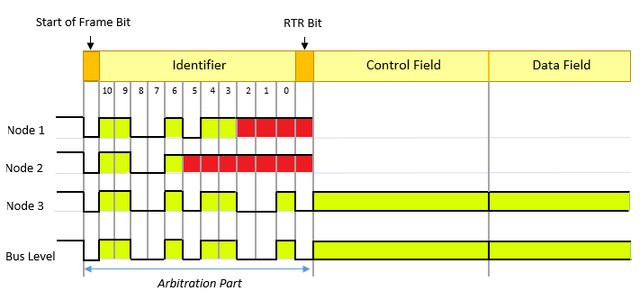
Fig. 26 Example of CAN arbitration. Author: Omid Avatefipour.#
The CAN Arbitration will always give priority to lower CAN identifier values, therefore it does not guarantee the starvation of high CAN identifiers. In the transmission context, starvation means a message can not be sent because other messages with higher priority are always present and therefore the message is delayed indefinitely. For this reason CAN bus systems are designed with less than 100% default load, to allow the recovery of the system after spikes in the communication.