ISO-TP#
Protocol Basics (ISO 15765-2)#
ISO 15765-2, also known as ISO-TP (ISO-15765 Transport Protocol), is a communication protocol used in the automotive industry to transmit data over a Controller Area Network (CAN) bus. It is designed to provide a reliable and efficient way to transfer large amounts of data, such as software updates and diagnostic data, over the CAN bus.
The protocol defines a set of rules for the data transfer, including the format of the data frames, the flow control mechanisms, and the error handling. The data frames are divided into smaller segments, called segments, which are transmitted over the CAN bus. The protocol also defines a set of flow control mechanisms, such as flow control frames, to handle situations where the receiver’s buffer is full.
ISO 15765-2 uses a multi-frame format, where a large message is divided into multiple smaller frames and sent over the bus. Each frame is identified by a unique ID, which allows the receiver to reassemble the frames in the correct order and to detect missing or duplicate frames.
Summary
Transport protocol for data transfer over CAN, FlexRay, LIN and MOST
Point-to-point communication
Up to \(2^{32}-1\) byte payloads (4GB)
Flow-Control management
No re-transmission functionality
Protocol Control Information (PCI)#
ISO-TP defines four special frame type
Frame type 0: SF (Single Frame)
Frame type 1: FF (First Frame)
Frame type 2: CF (Consecutive Frame)
Frame type 3: FC (Flow Control Frame)
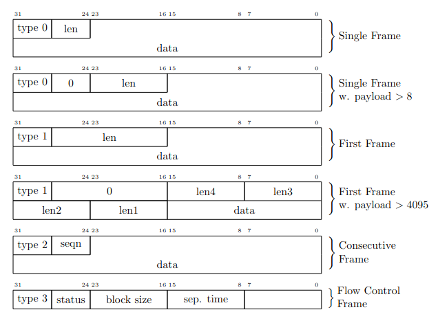
Fig. 45 Transport Layer (ISO-TP) frame types#
ISOTP-addressing#
The ISO-TP standard describes three different kinds of addressing: normal, extended, and mixed addressing [ISOCSecretary16]. Dependent on the addressing mode, the AI (Address Information) is encoded in different fields of a CAN frame. Also, the position of the protocol control information field varies, depending on the used addressing scheme. For further references in this paper, all addressing schemes will be identified with a label from the table following.
Ref. |
Description |
|---|---|
A1 |
Normal addressing, 11-bit CAN identifier |
A2 |
Normal fixed addressing, 29-bit CAN identifier |
A3 |
Extended addressing, 11-bit CAN identifier |
A4 |
Mixed addressing with 29-bit CAN identifier |
A5 |
Mixed addressing with 11-bit CAN identifier |
FC structure#
Flow-Control status (FS) codes:
0 = Clear to send
1 = Wait
2 = Overflow
Abbreviations:
AI: Address Information
PCI: Protocol Control Information
SA: Source Address
TA: Target Address
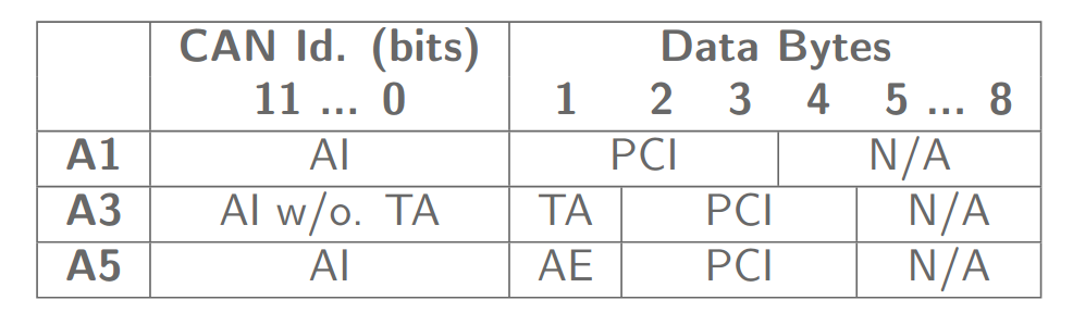
Fig. 46 Summary of flow control messages in 11-bit CAN identifier (CAN Id.) frames for normal (A1), extended (A3), and mixed addressing (A5) mode. Address Extension (AE)#
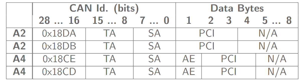
Fig. 47 Summary of flow control messages in 29-bit CAN identifier frames for normal fixed (A2) and mixed (A4) addressing mode with physical and functional addressing types.#
0x18DA = Const: Normal fixed addressing, physical 0x18DB = Const: Normal fixed addressing, functional 0x18CE = Const: Mixed addressing, physical 0x18CD = Const: Mixed addressing, functional
ISOTP addressing complexities#
Ref. |
||
|---|---|---|
A1 |
\(2^{11}\) |
\(2048\) |
A2 |
\(2 \times 2^8 \times 2^8 = 2^{17}\) |
\(131072\) |
A3 |
\(2^{11} \times 2^8 = 2^{19}\) |
\(524288\) |
A4 |
\(2 \times 2^8 \times 2^8 \times 2^8 = 2^{25}\) |
\(33554432\) |
A5 |
\(2^{11} \times 2^8 = 2^{19}\) |
\(524288\) |
Padding#
The ISOTP communication can be with or without padding. With padding every CAN frame is always 8 bytes long, if not all 8 bytes are needed, the rest is filled up with a predefined byte. Normally a “0xA” is used as padding since it will produce no stuffing bits on the CAN.
FC examples#
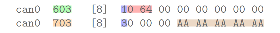
Fig. 48 Communication example of addressing scheme A1 captured with candump.#
The figure above highlights all ISO-TP communication parameters for addressing scheme A1. A FF (blue) message with SA 0x603 (green) and a packet size of 100 bytes (red) is sent on the CAN bus. An ISO-TP endpoint with TA 0x703 (orange) acknowledges the FF message with an FC message (blue). The CAN message length of 8 bytes indicates that this ISO-TP endpoint uses padding (brown). The addressing scheme can be determined by the position of the frame type identification (blue).
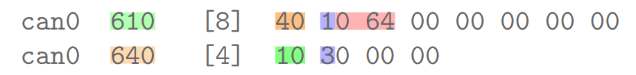
Fig. 49 Communication example of addressing scheme A3 or A5 captured with candump.#
Another example of addressing schemes A3 or A5 is given in the figure above. In real-world scenarios, these two addressing schemes are not deducible from their communication traffic. On the other hand, for the ISO-TP endpoint identification, it does not matter which one is used. Source and destination ISO-TP endpoint addresses are still encoded in the CAN identifier. Additionally, extended address information is encoded in the first payload byte of each CAN packet (dark orange and dark green). The ISO-TP frame type information is moved to byte position two of the CAN packet payload. This ISO-TP endpoint does not require padding, which can be seen from the shorter CAN message length of the receiver flow control acknowledgment.
ISOTP communication#

Fig. 50 ISO-TP fragmented communication#
First frame from sender
Sender waits for FC to send more data
Receiver sends FC after FF and if FC needs to update