Vehicle Networks#
Modern vehicles are more similar to a computer than to mechanical devices. Up to 100 different computers, called ECUs (Electronic Control Unit), connected by hundreds of cables (more than two kilometers of cable on average), shape a modern vehicle’s internal network. Additionally to these wired connections, multiple ECUs support wireless connectivity, mainly for convenience and emergency functionalities.
This chapter introduces relevant protocols and existing network topologies of recent vehicles. Used protocols in a vehicle’s network are introduced, and the relevance for security evaluations is discussed briefly.
Network Technologies#
More than 20 different communication protocols exist for the vehicle’s internal wired communication. Most vehicles make use of five to ten different protocols for their internal communication. The decision of which communication protocol is used by an OEM is usually made by the trade-off between the costs for communication technology, the final car price, and the desired features. The four major communication technologies for inter-ECU communication are CAN, FlexRay, LIN, and Automotive Ethernet. For security considerations, these are the most relevant protocols for wired communication in vehicles. Since MOST networks are only used to communicate multimedia payloads, MOST networks are not discussed in this book. Usually, safety-critical data is not communicated through MOST networks.
LIN#
LIN Connects ECUs with actuators and sensors
Single wire communication protocol
Low data rates
ECUs usually act as LIN master
Actuators and sensors act as LIN slave
Attacks were demonstrated [TAM+17]
Attack surface in general is very low
Propagation into further networks is very unlikely
LIN is a single-wire communication protocol for low data rates. Actuators and sensors of a vehicle exchange information with an ECU, acting as a LIN master. Software updates over LIN are possible, but the LIN slaves usually do not need software updates because of their limited functionality. This book excludes LIN as a protocol for security-relevant considerations. Attacks on LIN are possible [TAM+17], but the attack range is very limited. An attack propagation through LIN into a topologically higher network is unlikely and was not shown yet.
CAN#
Interconnects ECUs
By far the most used communication technology
Primary communication technology in older or cheaper vehicles
Safety-critical communication during a vehicle’s operation (drive by wire)
Diagnostic related communication in repair shops
Software updates during production or in repair shops
No security features in the protocol itself
Currently the primary protocol for security investigations
CAN is by far the most used communication technology for inter-ECU communication in vehicles. In older or cheaper vehicles, CAN is still the primary protocol for a vehicle’s backbone communication. Safety-critical communication during a vehicle’s operation, diagnostic information, and software updates are transferred between ECUs over CAN. The lack of security features in the protocol itself, combined with its general use, makes CAN the primary protocol for security investigations. (See chapter CAN)
FlexRay#
Interconnects safety-critical ECUs
Designed to become a successor of CAN
Higher communication bandwidth than CAN
Deterministic communication part with real-time support
Flexible communication part for high payloads, non-deterministic
FlexRay components are more expensive than CAN
No open-source hard- or software projects available
The FlexRay consortium designed FlexRay as a successor of CAN. Modern vehicles have higher demands on communication bandwidth. By design, FlexRay is a fast and reliable communication protocol for inter-ECU communication. FlexRay components are more expensive than CAN components, leading to a more selective use by OEMs. The lack of open-source hardware and software for FlexRay communication rules out the consideration of FlexRay in this book.
Automotive Ethernet#
Acts as vehicle backbone
Used as backbone technology in upper-class vehicles
Higher communication bandwidth than FlexRay
Deterministic communication part with real-time support
Only the physical layer (layer 1) differs from IEEE 802.3
Will probably make FlexRay obsolete
Automotive Ethernet (BroadR-Reach) uses two wire twisted pair cables
Recent upper-class vehicles implement Automotive Ethernet, the new backbone technology for internal vehicle communication. The rapidly grown bandwidth demands already replace FlexRay [SS18]. The primary reasons for these demands are driver-assistant and autonomous-driving features. Only the physical layer (layer 1) of the OSI model distinguishes Ethernet (IEEE 802.3) from Automotive Ethernet (BroadR-Reach). This design decision leads to multiple advantages. For example, communication stacks of high-level operating systems can be used without modification and routing, filtering, and firewall systems. Automotive Ethernet components are already cheaper than FlexRay components, which will lead to vehicle topologies, where CAN and Automotive Ethernet are the most used communication protocols. (See chapter Automotive Ethernet)
Topologies#
Line-Bus#
Only present in lower-priced or very old vehicles
All ECUs can directly talk to each other
No separation, no security
One vulnerable ECU can attack all others
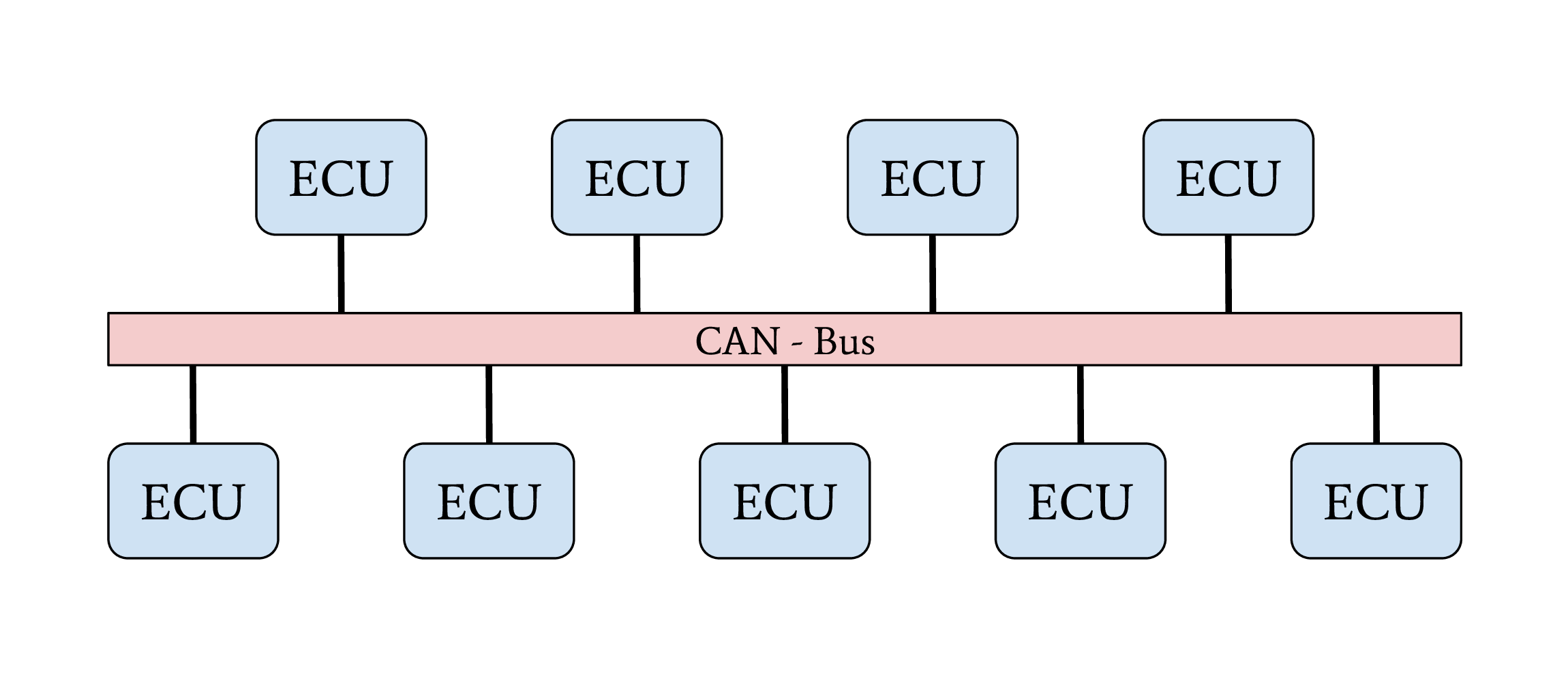
Fig. 5 Line-Bus network topology#
The first vehicles with CAN buses used a single network with a line-bus topology. Some lower-priced vehicles still use one or two shared CAN bus networks for their internal communication nowadays. The downside of this topology is its vulnerability and the lack of network separation. All ECUs of a vehicle are connected to a shared bus. Since CAN does not support security features from its protocol definition, any participant on this bus can communicate directly with all other participants, which allows an attacker to affect all ECUs, even safety-critical ones, by compromising one single ECU. The overall security level of this network is given from the security level of the weakest participant. The famous attack from Miller and Valasek was possible because this topology was used in the car they attacked [MV15]. Attackers can escalate an attack on a vulnerable ECU over the network to interfere directly with safety-critical ECUs.
Central Gateway#
Used in mid-priced cars
A central gateway separates individual domains
Difficult attack propagation from one domain to another
A vulnerable ECU can only affect it’s domain
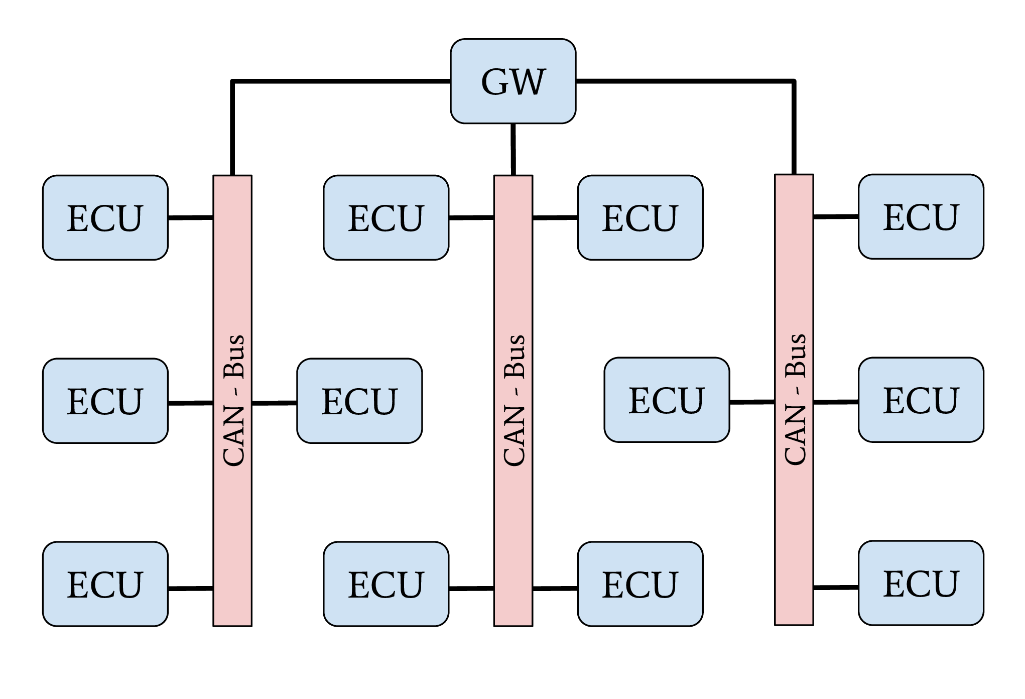
Fig. 6 Central gateway network topology#
The central GW topology can be found in higher-priced older cars and medium- to lower-priced recent cars. A centralized GW ECU separates domain-specific sub-networks. This allows an OEM to encapsulate all ECUs with remote attack surfaces in one sub-network. ECUs with safety-critical functionalities are located in an individual CAN network. Next to CAN, FlexRay might also be used as a communication protocol inside a separate network domain. The security of a safety-critical network in this topology depends mainly on the central GW ECU’s security. This architecture increases the overall security level of a vehicle through domain separation. After an attacker successfully exploited an ECU through an arbitrary attack surface, a second exploitable vulnerability or a logical bug is necessary to compromise a different domain, a safety-critical network, inside a vehicle. This second exploit or logical bug is necessary to overcome the network separation of the central GW ECU.
Central Gateway (GW) and Domain Controller (DC)#
Used in recent high-priced cars
A central gateway separates individual domains
Backbone communication between gateway and domain controller via automotive Ethernet
Domain controller acts as additional firewall
Features on demand are easy to implement
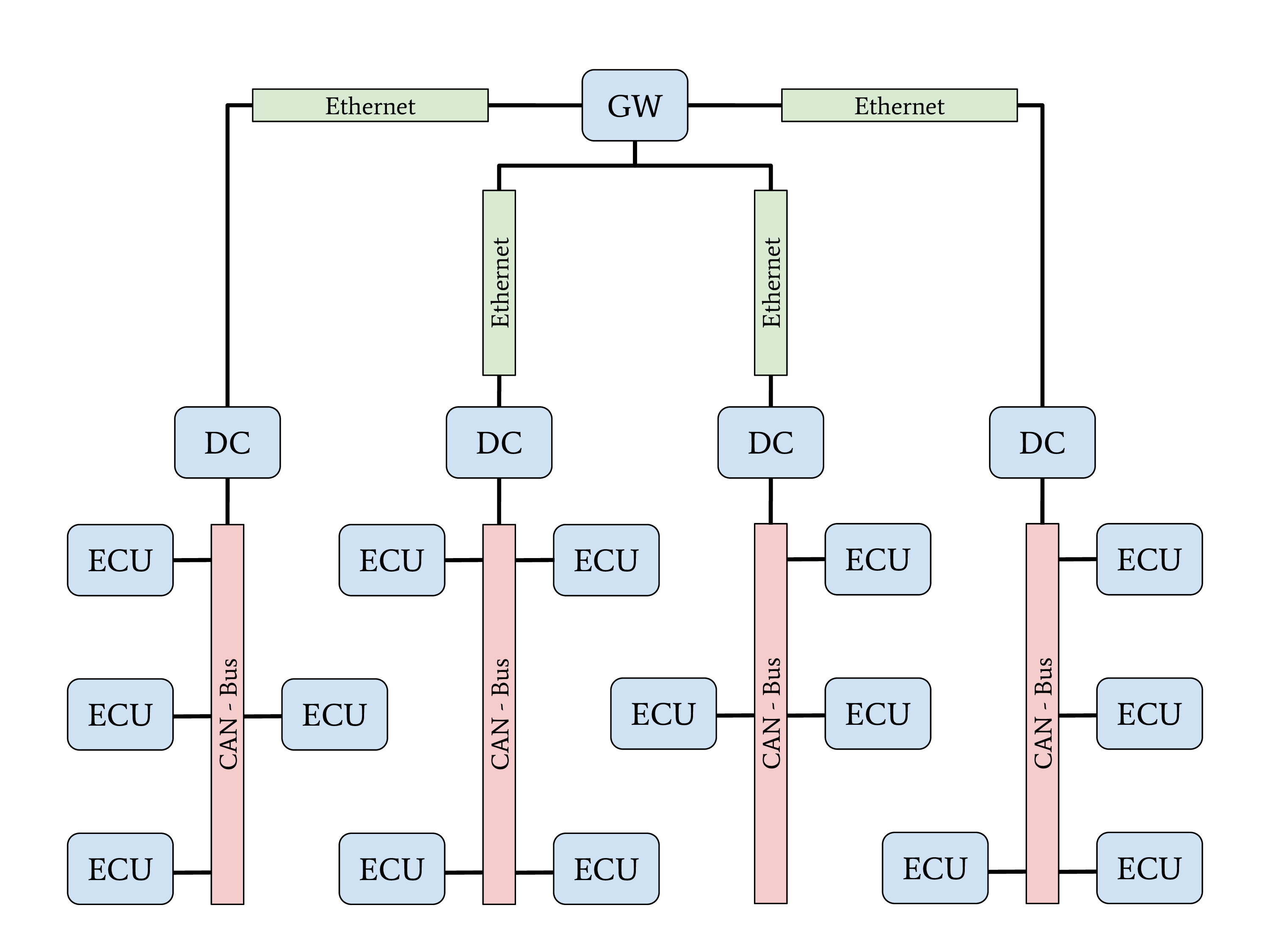
Fig. 7 Central gateway network topology with domain controllers#
A new topology with central GW and DCs can be found in the latest higher-priced vehicles. The general structure of this topology is shown in the figure above. The increasing demand for bandwidth in modern vehicles with autonomous driving and driver assistant features led to this topology. An Automotive Ethernet network is used as a communication backbone for the entire vehicle. Individual domains, connected through a DC with the central GW, form the vehicle’s backbone. The individual DCs can control and regulate the data communication between a domain and the vehicle’s backbone. This topology achieves a very-high security level through a strong network separation with individual DCs, acting as gateway and firewall, to the vehicle’s backbone network. OEMs have the advantage of dynamic information routing next to this security improvement, an enabler for Feature on Demand (FoD) services.
Zone-Controllers#
Currently, in development
High bandwidth network connects all zone controllers
Domains are defined in software and are seperated virtually at Zone-Switches
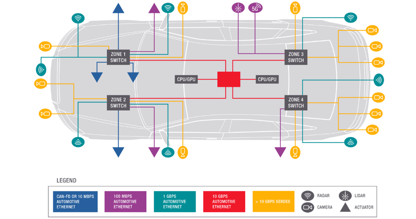
Fig. 8 A conceptual diagram of a zone-based in vehicle network architecture. Image: Keysight Technologies.#
The goal of zonal architectures is a lower complexity, cost, and weight of the wiring harness. This is achieved by a high-bandwidth one-to-one architecture at the core. Since the central computing complex is connected to the sensors and devices through Zone-Switches, a zonal approach will provide better scalability and improve reliability and functionality. This architecture enables the Software Defined Vehicle with for example Machine Learning on main Server, Data gathering over Zones, Virtual separation, etc. The computing power on the main server is also needed since in the future a lot more camera data via the high speed backbone needs to be computed.
Summary#
The topology of a vehicle’s network has a very high impact on a vehicle’s security and safety properties. Only a few vehicles from the lower price segment or higher age are still using one or two CANs for their internal communication. Most vehicles are equipped with a central GW ECU. After the publication of Miller and Valasek, even the cheapest cars received an upgrade of their internal network topology, and OEMs made use of central GW ECUs as mitigation for cyber-attacks. Only a few vehicles from the higher price segment already implement a network architecture with Automotive Ethernet as a communication backbone. Nevertheless, this group will rapidly grow soon since the advantages will compensate for the higher prices for communication equipment.