ISOTP Scanning techniques#
Details can be found in this paper: [WRMM20].
To identify all possible communication endpoints and their supported application layer protocols, a transport layer scan has to be performed first. Through the separation into the transport and application layers, every communication endpoint, no matter which application layer protocol it supports, can be identified. This applies even to the GMLAN protocol, where transport and application layer definitions are mixed. Sometimes, OEMs also use ISO-TP endpoints to exchange various data between ECUs. These endpoints use completely proprietary and unknown application layer protocols. Since our approach only targets the transport layer, even these endpoints can be identified on the network.
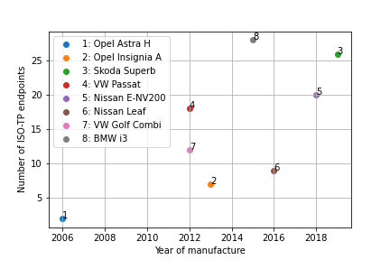
Fig. 53 Year of manufacturing and number identified ISO-TP endpoints#
The above figure clearly shows that more recent or higher priced cars contain more ISO-TP endpoints. An Opel Astra, built 2006, only has two different ISO-TP endpoints, whereby a Skoda Superb, built 2019, shows 26 different ISO-TP endpoints.
Active scanning#
Summary:
Can identify all ISO-TP endpoints on a bus
Causes high bus utilization
IDS will immediately see illegitimate traffic
May disturb safety-critical or real-time communication
No knowledge about the supported application layer protocol necessary
No knowledge about padding required
Procedure:
Choose an addressing scheme
Craft FF with payload length e.g. 100
Send FF with all possible addresses according to the chosen addressing scheme
Listen for FC frames according to the chosen addressing scheme
If FC is detected, obtain all address information and information about padding from the last FF and the received FC
This technique is suitable to identify all existing ISO-TP endpoints of a vehicle network or an ECU. An active scan will cause high utilization of the scanned CAN network. Any intrusion detection system will immediately identify an active scan as malformed communication. Therefore an active scan should be used with care since the onboard communication of a vehicle might be disturbed and even safety-critical or real-time communication could be interrupted or delayed.
To identify all ISO-TP endpoints, ISO-TP FFs of all possible addressing schemes and all possible address combinations are sent to the CAN network. Every ISO-TP endpoint that receives a correctly addressed FF (First Frame) has to answer with an FC (Flow Control) message. As soon as a corresponding FC is received on the CAN network, the communication parameters (addressing scheme, SA (Source Address), TA (Target Address), AE (Address Extension), padding) can be determined from the combination of the sent FF and received FC.
Passive scanning:#
Summary:
May only identify ISO-TP endpoints with active communication
May not detect all possible ISO-TP endpoints
A repair shop tester helps to trigger communication
Doesn’t interfere with the vehicle communication
Not detectable by IDS
Procedure:
Sniff a CAN bus and filter for FF and FC messages according to a chosen addressing scheme
If both messages were detected, extract address information
Passive scans have the advantage that no additional bus load is generated during the scan. On the other hand, it might be possible that not all existing ISO-TP endpoints are found since special ISO-TP endpoints might only be used during very rare situations of a vehicle’s life cycle. No communication to this special ISO-TP endpoint will show up in the vehicle’s network traffic. Another disadvantage of passive scans is that ISO-TP endpoints for diagnostic protocols are only used during operations in a repair shop or a car factory. This makes the presence of some additional tool that triggers diagnostic communication necessary to perform a passive ISO-TP scan. To conduct a passive scan, filters on the first and second byte of the CAN payload have to be applied. As soon as a FF is detected by the frame type indicator (0x1) in byte one or two of a CAN message payload, followed by another CAN message with a flow control frame type indicator as acknowledgment, an ISO-TP endpoint is found. The extraction of the relevant communication parameters is identical to the active ISO-TP scan.
in Scapy#
In this example, we use vcan0 interface.
Load necessary components in Scapy
from scapy.all import *
conf.contribs['ISOTP'] = {'use-can-isotp-kernel-module': True}
conf.contribs['CANSocket'] = {'use-python-can': False}
load_contrib('cansocket')
load_contrib('isotp')
Run scan
socks = isotp_scan(CANSocket("vcan0"), range(0x120, 0x130), can_interface="vcan0")
Show results
print(socks)
[<<ISOTPNativeSocket: read/write packets at a given CAN interface using CAN_ISOTP socket > at 0x7f25c963ab50>]